Yes. Vibration, hull movement, moisture, or changing electrical demand can disturb a marginal connection. Record the operating conditions when the fault occurs.

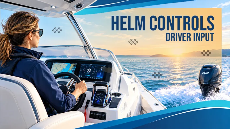
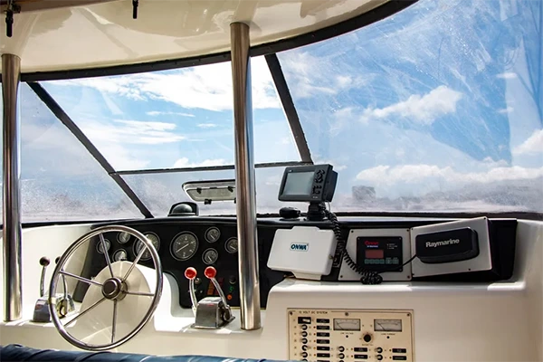
Modern outboard helm controls use sensors, actuators, and other components to detect driver’s actions, such as turning the wheel or moving the throttle, which are then converted into electric signals. These signals are processed and sent to the right components for steering control, speed, and gear. Now, the mechanical cables known for physically pulling an engine’s throttle are being largely replaced by wires, sensors, and computers, which use electronic signals to turn a driver’s simple input into a specific engine action.
Using Fly-by-Wire (FBW) technology, also known as Electronic Shift and Throttle (EST), it turns a simple movement of the steering wheel or throttle into an electric signal for precise engine actions. Sensors, actuators, and other components ensure that the engine responds correctly. Hence, it acts as a bridge between the driver’s signal and the engine’s action. Follow the article to learn more about how modern outboard helm connects driver input with engine action.
Marine controls can be mechanical, electrical, electronic, or a combination of all three. Although the technology and components may differ between boats, most successful control systems follow the same basic pattern: the operator requests an action, the system carries it out, and feedback confirms the result.
| Layer | Example component | Possible failure signal |
| Input | Key switch, control lever, trim button | No response, inconsistent movement, or lost detent |
| Control | Mechanical control box or electronic control head | Incorrect state or command not recognized |
| Transport | Control cable, harness, connector, or network link | Intermittent operation, lag, or communication warning |
| Execution | Starter circuit, shift actuator, throttle mechanism, trim motor | Command is received, but action does not occur |
| Feedback | Gauge, warning lamp, buzzer, or display | Missing, delayed, or inaccurate status information |
This is useful when comparing Honda outboard controls. The category includes panels, switches, control assemblies, and rigging-related components, each performing a specific role within the overall control system. Its appearance reveals only a small part of its function.
Fault isolation works backward from the result to identify where a problem may have occurred. If trim does not respond, the cause could sit at the button, connector, harness, power supply, relay, or trim unit. Replacing the switch before identifying the failed layer is simply a guess.
Two switch panels can share the same shape and button arrangement while being designed for different systems. They may use different connector pinouts, mounting patterns, warning circuits, or harness lengths. Even a plug that physically fits does not prove that its terminals carry the correct signals or that components will communicate properly. Hence, compatibility depends on electrical and control specifications, and not on whether two parts look similar.
The control architecture matters as well. A traditional mechanical lever moves the shift and throttle cables directly. Electrical circuits may separately manage ignition, emergency stop, warnings, and trim. A supported electronic system, such as Honda Intelligent Shift and Throttle, or iST, converts lever movement into a digital command that is interpreted and executed downstream.
That difference in control architecture affects both diagnosis and replacement. Stiffness in a mechanical setup may involve the lever, cable routing, adjustment, or engine linkage. An electronic lever can move normally, while another issue prevents the expected engine response. Problems with power supply, communication, calibration, sensor, or actuator may affect how the system responds.
A no-start condition is equally broad. The key or start switch may be involved, but so might the battery, neutral-start state, emergency-stop circuit, wiring, connector, or an engine-side component. Safety circuits should never be bypassed to narrow the search. Relevant parts of the system must be checked step by step with a proper troubleshooting process.
Approach the system as an engineer would approach a failed interface:
Intermittent faults require additional context. Note whether the problem appeared during startup, shifting, trim operation, rough water, or a station transfer. Vibration, moisture, and changing electrical load can expose a weak connection that behaves normally at the dock.
A layered model narrows the search without oversimplifying the system. It helps distinguish a failed input from a command that was transmitted correctly but not executed.
The method also offers three practical advantages:
For example, a working trim switch on the outboard but an unresponsive switch at the helm shifts attention toward the helm input and its transport path. It does not automatically condemn the complete control assembly.
Feedback deserves its own place in this model. Detents, indicator lamps, alarms, gauges, and display messages tell the operator whether a command was accepted. A failed warning lamp may not stop the engine, but if it fails, it removes information needed to interpret the engine’s state.
Choosing a control component is similar to checking a software dependency. The replacement must communicate with the surrounding system, support the required functions, and fit the existing installation.
Verify the following before ordering:
Price and panel shape should be considered only after compatibility has been confirmed. Changing one switch or control head does not upgrade the complete system, and mixing generations can leave essential functions unavailable. Some electronic components may also require calibration or configuration after installation.
Internal circuit testing, powered diagnostics, and electronic setup require the correct procedures and equipment. If the emergency-stop function, ignition circuit, or control authority is uncertain, installation and testing should be handled by a qualified marine technician.
Yes. Vibration, hull movement, moisture, or changing electrical demand can disturb a marginal connection. Record the operating conditions when the fault occurs.
Not necessarily. Digital displays can be installed alongside mechanical throttle and shift controls. Each subsystem must be identified separately.
Use only extension methods and components approved for the system. Length, conductor size, shielding, connector design, and communication requirements can all affect operation.
Multi-station systems need a defined method for transferring control authority. The switches, harnesses, and control logic must support the complete station layout.